Showing posts with label 2. Show all posts
Showing posts with label 2. Show all posts
Wednesday, October 2, 2013
2 Line Intercom Cum Telephone Line Changeover Circuit
The circuit presented here can be used for connecting two telephones in parallel and also as a 2-line intercom. Usually a single telephone is connected to a telephone line. If another telephone is required at some distance, a parallel line is taken for connecting the other telephone. In this simple parallel line operation, the main problem is loss of privacy besides interference from the other phone. This problem is obviated in the circuit presented here. Under normal condition, two telephones (telephone 1 and 2) can be used as intercom while telephone 3 is connected to the lines from exchange. In changeover mode, exchange line is disconnected from telephone 3 and gets connected to telephone 2. For operation in intercom mode, one has to just lift the handset of phone 1 and then press switch S1.
As a result, buzzer PZ2 sounds. Simultaneously, the side tone is heard in the speaker of handset of phone 1. The person at phone 2 could then lift the handset and start conversation. Similar procedure is to be followed for initiation of the conversation from phone 2 using switch S2. In this mode of operation, a 3-pole, 2-way slide-switch S3 is to be used as shown in the figure. In the changeover mode of operation, switch S3 is used to changeover the telephone line for use by telephone 2. The switch is normally in the intercom mode and telephone 3 is connected to the exchange line. Before changing over the exchange line to telephone 2, the person at telephone 1 may inform the person at telephone 2 (in the intercom mode) that he is going to changeover the line for use by him (the person at telephone 2).
 As soon as changeover switch S3 is flipped to the other position, 12V supply is cut off and telephones 1 and 3 do not get any voltage or ring via the ring-tone-sensing unit. Once switch S3 is flipped over for use of exchange line by the person at telephone 2, and the same (switch S3) is not flipped back to normal position after a telephone call is over, the next telephone call via exchange lines will go to telephone 2 only and the ringtone-sensing circuit will still work. This enables the person at phone 3 to know that a call has gone through. If the handset of telephone 3 is lifted, it is found to be dead. To make telephone 3 again active, switch S3 should be changed over to its normal position.
Continue Reading[...]
As a result, buzzer PZ2 sounds. Simultaneously, the side tone is heard in the speaker of handset of phone 1. The person at phone 2 could then lift the handset and start conversation. Similar procedure is to be followed for initiation of the conversation from phone 2 using switch S2. In this mode of operation, a 3-pole, 2-way slide-switch S3 is to be used as shown in the figure. In the changeover mode of operation, switch S3 is used to changeover the telephone line for use by telephone 2. The switch is normally in the intercom mode and telephone 3 is connected to the exchange line. Before changing over the exchange line to telephone 2, the person at telephone 1 may inform the person at telephone 2 (in the intercom mode) that he is going to changeover the line for use by him (the person at telephone 2).
 As soon as changeover switch S3 is flipped to the other position, 12V supply is cut off and telephones 1 and 3 do not get any voltage or ring via the ring-tone-sensing unit. Once switch S3 is flipped over for use of exchange line by the person at telephone 2, and the same (switch S3) is not flipped back to normal position after a telephone call is over, the next telephone call via exchange lines will go to telephone 2 only and the ringtone-sensing circuit will still work. This enables the person at phone 3 to know that a call has gone through. If the handset of telephone 3 is lifted, it is found to be dead. To make telephone 3 again active, switch S3 should be changed over to its normal position.
Monday, September 2, 2013
2 Cell Lithium Ion Charger
This circuit was build to charge a couple series Lithium cells (3.6 volts each, 1 Amp Hour capacity) installed in a portable transistor radio. The charger operates by supplying a short current pulse through a series resistor and then monitoring the battery voltage to determine if another pulse is required. The current can be adjusted by changing the series resistor or adjusting the input voltage.
When the battery is low, the current pulses are spaced close together so that a somewhat constant current is present. As the batteries reach full charge, the pulses are spaced farther apart and the full charge condition is indicated by the LED blinking at a slower rate. A TL431, band gap voltage reference (2.5 volts) is used on pin 6 of the comparator so the comparator output will switch low, triggering the 555 timer when the voltage at pin 7 is less than 2.5 volts.
The 555 output turns on the 2 transistors and the batteries charge for about 30 milliseconds. When the charge pulse ends, the battery voltage is measured and divided down by the combination 20K, 8.2K and 620 ohm resistors so when the battery voltage reaches 8.2 volts, the input at pin 7 of the comparator will rise slightly above 2.5 volts and the circuit will stop charging.
2 Cell Lithium Ion Charger Circuit diagram
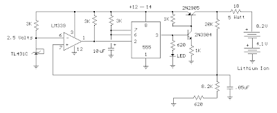
The circuit could be used to charge other types of batteries such as Ni-Cad, NiMh or lead acid, but the shut-off voltage will need to be adjusted by changing the 8.2K and 620 ohm resistors so that the input to the comparator remains at 2.5 volts when the terminal battery voltage is reached. For example, to charge a 6 volt lead acid battery to a limit of 7 volts, the current through the 20K resistor will be (7-2.5)/ 20K = 225 microamps. This means the combination of the other 2 resistors (8.2K and 620) must be R=E/I = 2.5/ 225 uA = 11,111 ohms. But this is not a standard value, so you could use a 10K in series with a 1.1K, or some other values that total 11.11K
Be careful not to overcharge the batteries. I would recommend using a large capacitor in place of the battery to test the circuit and verify it shuts off at the correct voltage.
When the battery is low, the current pulses are spaced close together so that a somewhat constant current is present. As the batteries reach full charge, the pulses are spaced farther apart and the full charge condition is indicated by the LED blinking at a slower rate. A TL431, band gap voltage reference (2.5 volts) is used on pin 6 of the comparator so the comparator output will switch low, triggering the 555 timer when the voltage at pin 7 is less than 2.5 volts.
The 555 output turns on the 2 transistors and the batteries charge for about 30 milliseconds. When the charge pulse ends, the battery voltage is measured and divided down by the combination 20K, 8.2K and 620 ohm resistors so when the battery voltage reaches 8.2 volts, the input at pin 7 of the comparator will rise slightly above 2.5 volts and the circuit will stop charging.
2 Cell Lithium Ion Charger Circuit diagram
The circuit could be used to charge other types of batteries such as Ni-Cad, NiMh or lead acid, but the shut-off voltage will need to be adjusted by changing the 8.2K and 620 ohm resistors so that the input to the comparator remains at 2.5 volts when the terminal battery voltage is reached. For example, to charge a 6 volt lead acid battery to a limit of 7 volts, the current through the 20K resistor will be (7-2.5)/ 20K = 225 microamps. This means the combination of the other 2 resistors (8.2K and 620) must be R=E/I = 2.5/ 225 uA = 11,111 ohms. But this is not a standard value, so you could use a 10K in series with a 1.1K, or some other values that total 11.11K
Be careful not to overcharge the batteries. I would recommend using a large capacitor in place of the battery to test the circuit and verify it shuts off at the correct voltage.
Subscribe to:
Posts (Atom)