Showing posts with label transmitter. Show all posts
Showing posts with label transmitter. Show all posts
Thursday, September 12, 2013
Simple FM Transmitter Circuit Diagram
This circuit is a simple two transistor (2N2222) FM transmitter. No license is required for this transmitter according to FCC regulations regarding wireless microphones. If powered by a 9 volt battery and used with an antenna no longer than 12 inches, the transmitter will be within the FCC limits.
The microphone is amplified by Q1. Q2, C5, and L1 form an oscillator that operates in the 80 to 130 MHz range. The oscillator is voltage controlled, so it is modulated by the audio signal that is applied to the base of Q2. R6 limits the input to the RF section, and its value can be adjusted as necessary to limit the volume of the input. L1 and C6 can be made with wire and a pencil. The inductor (L1) is made by winding two pieces of 24 gauge insulated wire, laid side by side, around a pencil six times. Remove the coil you have formed and unscrew the two coils apart from each other.
FM Transmitter Circuit Diagram
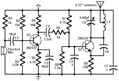
One of these coils (the better looking of the two) will be used in the tank circuit, and the other can be used in the next one you build. The antenna (24 gauge wire) should be soldered to the coil you made, about 2 turns up from the bottom, on the transistor side, and should be 8-12 inches long. To make C6, take a 4 inch piece of 24 gauge insulated wire, bend it over double and, beginning 1/2" from the open end, twist the wire as if you were forming a rope. When you have about 1" of twisted wire, stop and cut the looped end off, leaving about 1/2" of twisted wire (this forms the capacitor) and 1/2" of untwisted wire for leads.

Friday, March 29, 2013
The AM Transmitter Circuit for 500 KHz to 1600 KHz
This circuit is design for AM transmitter circuit. This circuit is operate for medium wave band for amplitude modulation. The operation of the circuit is in below.

The circuit is in two half, an audio amplifier and an RF oscillator. The oscillator is built around Q1 and associated components. The tank circuit L1 and VC1 is tunable from about 500 KHz to 1600 KHz. These components can be used from an old MW radio, if available. Q1 needs regenerative feedback to oscillate and this is achieved by connecting the base and collector of Q1 to opposite ends of the tank circuit. The 1nF capacitor C7, couples signals from the base to the top of L1, and C2, 100pF ensures that the oscillation is passed from collector, to the emitter, and via the internal base emitter resistance of the transistor, back to the base again. Resistor R2 has an important role in this circuit. It ensures that the oscillation will not be shunted to ground via the very low internal emitter resistance, re of Q1, and also increases the input impedance so that the modulation signal will not be shunted. Oscillation frequency is adjusted with VC1.
The Q2 is wired as a common emitter amplifier, C5 decoupling the emitter resistor and realizing full gain of this stage. The microphone is an electret condenser mic and the amount of AM modulation is adjusted with the 4.7k preset resistor P1. An antenna is not needed, but 30cm of wire may be used at the collector to increase transmitter range.
The circuit is in two half, an audio amplifier and an RF oscillator. The oscillator is built around Q1 and associated components. The tank circuit L1 and VC1 is tunable from about 500 KHz to 1600 KHz. These components can be used from an old MW radio, if available. Q1 needs regenerative feedback to oscillate and this is achieved by connecting the base and collector of Q1 to opposite ends of the tank circuit. The 1nF capacitor C7, couples signals from the base to the top of L1, and C2, 100pF ensures that the oscillation is passed from collector, to the emitter, and via the internal base emitter resistance of the transistor, back to the base again. Resistor R2 has an important role in this circuit. It ensures that the oscillation will not be shunted to ground via the very low internal emitter resistance, re of Q1, and also increases the input impedance so that the modulation signal will not be shunted. Oscillation frequency is adjusted with VC1.
The Q2 is wired as a common emitter amplifier, C5 decoupling the emitter resistor and realizing full gain of this stage. The microphone is an electret condenser mic and the amount of AM modulation is adjusted with the 4.7k preset resistor P1. An antenna is not needed, but 30cm of wire may be used at the collector to increase transmitter range.
Subscribe to:
Posts (Atom)