Showing posts with label simple. Show all posts

Wednesday, December 25, 2013

Simple Microprocessor power supply watchdog circuit Diagram

The Simple Microprocessor power supply watchdog circuit Diagram monitors the input to the microprocessor 5 V regulated supply for voltage drops and initiates a reset sequence before supply regulation is lost. In operation, the resistor capacitor combination Rs and Cj form a short time constant smoothing network for the output of the fullwave bridge rectifier. 

An approximately triangular, voltage waveform appears across C and Rs and it is the minimum excursion of this that initiates the reset. Diode Dg prevents charge sharing between capacitors Cj and Ck. Resistors Rn and Rm form a feedback network around the voltage reference section of the LM10C, setting a threshold voltage of 3.4 volts. 

 Microprocessor power supply watchdog circuit Diagram

Simple Microprocessor power supply watchdog circuit Diagram


The threshold voltage is set at 90% of the minimum voltage of the triangular waveform. When the triangular wave trough, at the comparators non-inverting input, dips below the threshold, the comparator output is driven low. This presents a reset to the microprocessor. Capacitor Ch is charged slowly through resistor Rk and discharged rapidly through diode De.
Continue Reading[...]

Thursday, September 12, 2013

Simple FM Transmitter Circuit Diagram

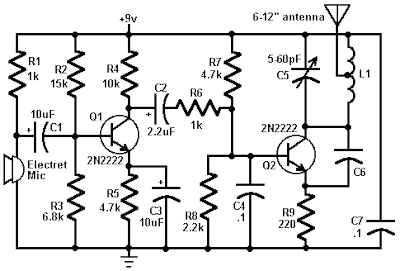
This circuit is a simple two transistor (2N2222) FM transmitter. No license is required for this transmitter according to FCC regulations regarding wireless microphones. If powered by a 9 volt battery and used with an antenna no longer than 12 inches, the transmitter will be within the FCC limits.

The microphone is amplified by Q1. Q2, C5, and L1 form an oscillator that operates in the 80 to 130 MHz range. The oscillator is voltage controlled, so it is modulated by the audio signal that is applied to the base of Q2. R6 limits the input to the RF section, and its value can be adjusted as necessary to limit the volume of the input. L1 and C6 can be made with wire and a pencil. The inductor (L1) is made by winding two pieces of 24 gauge insulated wire, laid side by side, around a pencil six times. Remove the coil you have formed and unscrew the two coils apart from each other. 

  FM Transmitter Circuit Diagram

  FM Transmitter Circuit Diagram


One of these coils (the better looking of the two) will be used in the tank circuit, and the other can be used in the next one you build. The antenna (24 gauge wire) should be soldered to the coil you made, about 2 turns up from the bottom, on the transistor side, and should be 8-12 inches long. To make C6, take a 4 inch piece of 24 gauge insulated wire, bend it over double and, beginning 1/2" from the open end, twist the wire as if you were forming a rope. When you have about 1" of twisted wire, stop and cut the looped end off, leaving about 1/2" of twisted wire (this forms the capacitor) and 1/2" of untwisted wire for leads.
Continue Reading[...]

Saturday, August 31, 2013

Simple Field Strength Meter

This Field Strength Meter is simple and also quite sensitive. It uses an ordinary digital voltmeter to measure RF signal strength up to a few hundred MHz.


Simple Field Strength Meter Circuit diagram:


Parts List:

1 OA91 Germanium Diode
1 3.3M Resistor
1 100p Capacitor
L1 7 turns on a 1/4 inch former (suitable for around 100MHz)

Notes:

The multimeter should be set to the lowest dc volts range for maximum sensitivity. This is normally 200mV DC for most meters. The circuit works well at VHF (around 100MHz) and was quite pleased with the results. L1 was 7 turns on a quarter inch former with ferrite slug. This covered the UK FM band.

A digital multimeter, as opposed to an analogue signal meter offers several advantages in this circuit. First, the impedance of a digital meter is very high, around 10Meg/Volt on most meters. This does not shunt the tank circuit unduly. Second, compared to an analogue meter, very slight differences in signal strength can be more easily observed. Thirdly,a digital meter will have better linearity, responding well to both weak and stronger signals.
Continue Reading[...]

Sunday, August 11, 2013

Simple Output limiter Circuit Diagram

Simple Output-limiter Circuit Diagram HA-5190 is rated for ±5 V output swing, and saturates at ±7 V. As with most op amps, recovery from output saturation is slow compared to the amplifier`s normal response time. Some form of limiting, either of the input signal or in the feedback path, is desirable if saturation might occur. The circuit illustrates a feedback limiter, where gain is reduced ifthe output exceeds ± ( Vz + 21j-). A 5-V zener with a sharp knee characteristic is recommended. 

Simple Output-limiter Circuit Diagram

Simple Output-limiter Circuit Diagram

Continue Reading[...]

Monday, May 27, 2013

Simple Water Level Detector

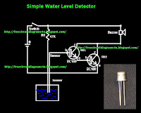
This is so useful circuit diagram because this circuit helps us to detect water.When the water come and touch the sensors it will make a sound.Here I have used common transistor bc109. Actually you can modify this circuit.. By using a relay you can switch on or off your water motor I will tell you them in my next post.

Note

# Use 6V to power this circuit
# The distance between the circuit and the sensors should be short.
# Build this circuit on a pcb to get good result.
Continue Reading[...]

Saturday, April 13, 2013

Simple Cheap LED flasher


This two LED flasher circuit uses any DC supply from 3V to 12V. Flash rate is controlled by R1,C1 and R2,C2. Larger values create slower fash rates, smaller values higher flash rates.
Continue Reading[...]

Friday, April 12, 2013

Simple Transistor Tester

This non transistor tester circuit devices that isn’t accurate, but utility of this test device enough assisting in assaying of quality of transistor. This circuit can show promise about condition of a transistor is still in condition either or have been in condition of breakdown. Besides, earns also applied to test amplification of current from the transistor is categorizing transistor type A (amplifier of current 140 - 270), transistor type B (270 - 500), or transistor type C (amplification > 500).

For example earns we to take a n p-n transistor as transistor which will be tested. The transistor packed into socket appropriate TUT = Transistor Under Test) hereinafter switches S2 is attached according to at schematic. If LED D2 blazed, hence the transistor is type C, medium if LED didnt ON, switches S2 must be removed on course middle and if still had not blazed, removes switches to last position. If LED is ON at course last switches, means transistor is type A.

On the contrary, if LED remaining to extinguish though had been tested at all of position of switches, hence transistor had been in condition of breakdown or has amplification of current smaller than 140, so that for transistor having small signal basically cann’t be utilized. Bases current to transistor is being tested able to be broken by using switches using compress switches. If LED still in condition blazed, means happened links shortening between colector and emitor at the transistor.

This very simple circuit work principle. Transistor tested receives bases current around 10mA through R1. With assumption that transistor is still be good, the thing will yield strain at R2 until R4 and depend on position of switches S2, some of this voltage compared to to a reference voltage by utilizing IC 1. Mode of action from circuit which its inside is also approximately equal, only inside of circuit destined for PNP transistor. The supply of the voltage is required by this circuit only from battery.


Continue Reading[...]

Thursday, April 11, 2013

Simple MD Catridge Preamplifier

Phonographs are gradually becoming a rarity. Most of them have had to yield to more advanced systems, such as CD players and recorders or (portable) MiniDisc player/recorders. This trend is recognized by manufacturers of audio installations, which means that the traditional phono input is missing on increasingly more systems. Hi-fi enthusiasts who want make digital versions of their existing collections of phonograph records on a CD or MD, discover that it is no longer possible to connect a phonograph to the system.

Simple MD Catridge Preamplifier circuit diagramHowever, with a limited amount of circuitry, it is possible to adapt the line input of a modern amplifier or recorder so that it can handle the low-level signals generated by the magnetodynamic cartridge of a phonograph. Of course, the circuit has to provide the well-known RIAA correction that must be used with these cartridges. The preamplifier shown here performs the job using only one opamp, four resistors and four capacitors. For a stereo version, you will naturally need two of everything. Any stabilized power supply that can deliver ±15V can be used as a power source.
Continue Reading[...]

Simple Mini Bench Supply

Every electronics engineer is familiar with the anxiety of the moment when power is first applied to a newly-built circuit, wondering whether hours of work are about to be destroyed in a puff of smoke. A high-quality power supply with an adjustable current limit function is an excellent aid to steadying the nerves. Unfortunately power supplies with good regulation performance are expensive and homebrew construction is not always straightforward. Many of the ‘laboratory power supplies’ currently on the market are low-cost units based on switching regulators which, although certainly capable of delivering high currents, have rather poor ripple performance. Large output capacitors (which, in the case of a fault, will discharge into your circuit) and voltage over-shoot are other problems.

The power supply described here is a simple unit, easily constructed from standard components. It is only suitable for small loads but otherwise has all the characteristics of its bigger brethren. Between 18 V and 24 V is applied to the input, for example from a laptop power supply. This avoids the need for an expensive transformer and accompanying smoothing. No negative supply is needed, but the output voltage is nevertheless adjustable down to 0 V.  

A difficulty in the design of power supplies with current limiting is the shunt resistor needed to measure the output current, normally connected to a differential amplifier. Frequently in simple designs the amplifier is not powered from a regulated supply, which can lead to an unstable current regulation loop. This circuit avoids the difficulty by using a low-cost fixed voltage regulator to supply the feedback circuit with a stable voltage. This arrangement greatly simplifies current measurement and regulation. 

Mini Bench Supply Circuit Diagram
Mini Bench-Supply-Circuit Diagram
To generate this intermediate supply volt-age we use an LM7815. Its output passes through R17, which measures the output current, to MOSFET T1 which is driven by the voltage regulation opamp IC1C. Here R11 and C4 determine the bandwidth of the control loop, preventing oscillation at high frequencies. R15 ensures that capacitive loads with low effective resistance do not make the control loop unstable.

 The negative feedback of AC components of the current via R12 and C5 makes the circuit reliable even with a large capacitor at its output, and negative feedback of the DC component is via the low-pass filter formed by R14 and C6. This ensures that the volt-age drop across R15 is correctly compensated for. C7 at the output provides a low impedance source for high-frequency loads, and R16 provides for the discharge of C17 when the set voltage is reduced with no load attached. 

Current regulation is carried out by IC1D. Again to ensure stability, the bandwidth of the feedback loop is restricted by R19 and C8. If the voltage dropped across R17 exceeds the value set by P2, the current limit function comes into action and T2 begins to conduct. This in turn reduces the input voltage to the voltage regulation circuit until the desired current is reached. R7, R9 and C3 ensure that current regulation does not lead to output voltage over-shoots and that resonance does not occur with inductive loads. 

The controls of the power supply are all voltage-based. This means, for example¸ that P1 and P2 can be replaced by digital-to-analogue converters or digital potentiometers so that the whole unit can be driven by a microcontroller. IC1B acts as a buffer to ensure that the dynamic characteristics of the circuit are not affected by the setting of P1. IC1A is used as a comparator whose out-put is used to drive two LEDs that indicate whether the supply is in voltage regulation or current regulation mode. If D2 lights the supply is in constant voltage mode; if D1 lights it is in constant current mode, for example if the output has been short-circuited. The power supply thus boasts all the features of a top-class bench supply.IC1A and its surrounding circuitry can be dispensed with if the mode indication is not wanted. 

A type LM324 operational amplifier is suggested as, in contrast to many other similar devices, it operates reliably with input voltages down to 0 V. Other rail-to-rail opamps could equally well be used. The particular n-channel MOSFET devices used are not critical: a BUZ21, IRF540, IRF542 or 2SK1428 could be used for T1, for example, and a BS170 could be used in place of the 2N7002. The capacitors should all be rated for a voltage of 35 V or higher, and R15 and R17 must be at least 0.5 W types. The fixed voltage regulator and T1 must both be equipped with an adequate heatsink. If they are mounted on the same heatsink, they must be isolated from it as the tabs of the two devices are at different potentials. 


Author : Alexander Mumm - Copyright : Elektor
Continue Reading[...]

Wednesday, April 10, 2013

Simple Over Current Indicator

This circuit eventually surfaced while pondering over the design of a current indicator for a small power supply. Fortunately, it proved possible to employ the supply voltage as a reference by dividing it down with the aid of R1 and R2. C1 is an essential capacitor to suppress noise and surges. The half supply voltage level is applied to the non-inverting pin of opamp IC1. The value of the R3 determines the trip level of the indicator, according to

R3 = 0.4 × (desired voltage drop) / I trip

Actually this is high side sensing but the method can be used as low side sensing, too! The desired voltage or sense voltage can be any value between 0.35 V and 0.47 V. If currents greater than about 1A are envisaged, you should not forget to calculate R3’s dissipation on penalty of smoke & smells.

Simple Overcurrent Indicator circuit diagramAnother voltage divider network, R4, R5 and P1 divide the voltage between supply voltage and desired oltage. This divided voltage, filtered by C2, is fed to the inverting input of IC1 to compare levels. The result causes D1 to light or remain off. Turn P1 to the end of R4 to hold off D1. Then connect a load causing over current and adjust P1 towards the end of R5 until D1 lights. The accuracy of the circuit depends entirely on the tolerances of the resistors used - high stability types are recommended.


Source by : Streampowers
Continue Reading[...]

Sunday, April 7, 2013

Simple Source Voltage Protector

Simple Source Voltage Protector
Protection of electronic devices with a DC voltage source of voltage source obligatory reversal, especially protection of the source voltage is reversed. The definition of "Protectors Voltage Sources" in this article are the source voltage surge protector circuit which serves to protect the device from the reversal of the voltage source to the appliance electronics.

Source voltage surge protector will expressed in this article are general, so that later in their applications to stay adjusted value of the component with the voltage source needs an electronic appliance. Let us start reviewing Protectors Voltage Source by simple and modest.

Source voltage protection with 1 diode


Diodes are used as a protector of the source voltage installation tebaliknya voltage source is installed in series with the input line voltage source electronics devices. Installation of surge protector diode as a voltage source is on the positive line voltage source input device. The function is to drain diode current (voltage source) in one direction only, so that in the event of an upside-down voltage source. then the voltage source is not in the channel (in blocks) to the device. The value of the diode is tailored to the needs of the source voltage of the device itself.

Source voltage protection with dioda bridge


Protectors voltage source with a diode bridge in principle the same as the surge protector with a voltage source diode 1 pc. The difference is the source voltage surge protector is not blocking the source voltage, but the source voltage surge protector is to reverse the flow of the source voltage of one polarity in the case of voltage source. From the picture above to explain the purpose of reversing the voltage source in question, namely when given a source voltage through a voltage surge protector is the source of positive polarity (+) will be directly in the stream leading to the positive input line of tools and the source of negative voltage (-) will be directed to the negative voltage source input line tool.
Continue Reading[...]

A Simple Fog Lamp Sensor

For several years now, a rear fog lamp has been mandatory for trailers and caravans in order to improve visibility under foggy conditions. When this fog lamp is switched on, the fog lamp of the pulling vehicle must be switched of to avoid irritating reflections. For this purpose, a mechanical switch is now built into the 13-way female connector in order to switch of the fog lamp of the pulling vehicle and switch on the fog lamp of the trailer or caravan. For anyone who uses a 7-way connector, this switching can also be implemented electronically with the aid of the circuit illustrated here.

Fog Lamp Sensor Circuit Diagram

Fog Lamp Sensor Circuit Daigram

Here a type P521 optocoupler detects whether the fog lamp of the caravan or trailer is connected. If the fog lamp is switched on in the car, a current flows through the caravan fog lamp via diodes D1 and D2. This causes the LED in the optocoupler to light up, with the result that the photo-transistor conducts and energies the relay via transistor T1. The relay switches of the fog lamp of the car. For anyone who’s not all thumbs, this small circuit can easily be built on a small piece of perforated circuit board and then fitted somewhere close to the rear lamp fitting of the pulling vehicle.

Source: http://www.ecircuitslab.com/2011/06/simple-fog-lamp-sensor.html
Continue Reading[...]

Thursday, April 4, 2013

Simple Current Regulator Circuit Using LM10


The current regulator is a bit unusual in that the supply current of the IC flows through the sense resistor and does not affect accuracy as long as it is less than the desired output current. It is also possible to use remote amplifiers with two-wire signal transmission, as was done with the comparators. Remote sensors can be particularly troublesome when low-level analog signals are involved. Transmission problems include induced noise, ground currents, shunting from cable capacitance, resistance drops and thermoelectric potentials. These problems can be largely eliminated by amplifying the signal at the source and altering impedances to levels more suitable for transmission. Here is a schematic drawing :
Continue Reading[...]

Monday, April 1, 2013

Simple 16 Stage Bi Directional LED Sequencer

The bi-directional sequencer uses a 4 bit binary up/down counter (CD4516) and two "1 of 8 line decoders" (74HC138 or 74HCT138) to generate the popular "Night Rider" display. A Schmitt Trigger oscillator provides the clock signal for the counter and the rate can be adjusted with the 500K pot. Two additional Schmitt Trigger inverters are used as a SET/RESET latch to control the counting direction (up or down). Be sure to use the 74HC14 and not the 74HCT14, the 74HCT14 may not work due to the low TTL input trigger level. When the highest count is reached (1111) the low output at pin 7 sets the latch so that the UP/DOWN input to the counter goes low and causes the counter to begin decrementing. 

When the lowest count is reached (0000) the latch is reset (high) so that the counter will begin incrementing on the next rising clock edge. The three lowest counter bits (Q0, Q1, Q2) are connected to both decoders in parallel and the highest bit Q3 is used to select the appropriate decoder. The circuit can be used to drive 12 volt/25 watt lamps with the addition of two transistors per lamp as shown below in the section below titled "Interfacing 5 volt CMOS to 12 volt loads"

Continue Reading[...]

Sunday, March 31, 2013

How to Make a Simple Active Low Pass Filter Circuit Using IC 741


In electronics, filter circuits are basically employed for restricting the passage of a certain frequency range while allowing some other band of frequency into the further stages of the circuit.


Primarily there are three types of frequency filters that are used for the above mentioned operations.

These are: Low pass filter, high pass filter and the band pass filter.
 As the name suggests, a low pass filter circuit will allow all frequencies below a certain set frequency range.
A high pass filter circuit will allow only the frequencies which are higher than the preferred set range of frequency while a band pass filter will allow only an intermediate band of frequencies to flow to the next stage, inhibiting all frequencies which may be outside this set range of oscillations.

Filters are generally made with two types of configurations, the active type and the passive type.
Passive type filter are less efficient and involve complicated inductor and capacitor networks, making the unit bulky and undesirable. However these will not require any power requirement for itself to operate, a benefit too small to be considered really useful.
Contrary to this active type of filters are very efficient, can be optimized to the point and are less complicated in terms of component count and calculations.

In this article we are discussing a very simple circuit of a low pass filter, which was requested by one of our avid readers Mr.Bourgeoisie.

Looking at the circuit diagram we can see a very easy configuration consisting of a single opamp as the main active component.
The resistors and the capacitors are discretely dimensioned for a 50 Hz cut OFF, meaning no frequency above 50 Hz will be allowed to pass through the circuit into the output.
For technical explanation of the circuit you may refer to the data provided here.
Continue Reading[...]