Wednesday, September 4, 2013
Dual Level Liquid Sensor
Dual Level Liquid Sensor Circuit Diagram


Monday, September 2, 2013
2 Cell Lithium Ion Charger
When the battery is low, the current pulses are spaced close together so that a somewhat constant current is present. As the batteries reach full charge, the pulses are spaced farther apart and the full charge condition is indicated by the LED blinking at a slower rate. A TL431, band gap voltage reference (2.5 volts) is used on pin 6 of the comparator so the comparator output will switch low, triggering the 555 timer when the voltage at pin 7 is less than 2.5 volts.
The 555 output turns on the 2 transistors and the batteries charge for about 30 milliseconds. When the charge pulse ends, the battery voltage is measured and divided down by the combination 20K, 8.2K and 620 ohm resistors so when the battery voltage reaches 8.2 volts, the input at pin 7 of the comparator will rise slightly above 2.5 volts and the circuit will stop charging.
2 Cell Lithium Ion Charger Circuit diagram
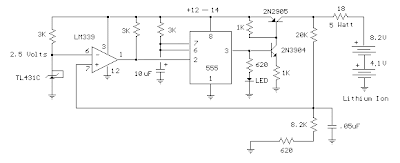
The circuit could be used to charge other types of batteries such as Ni-Cad, NiMh or lead acid, but the shut-off voltage will need to be adjusted by changing the 8.2K and 620 ohm resistors so that the input to the comparator remains at 2.5 volts when the terminal battery voltage is reached. For example, to charge a 6 volt lead acid battery to a limit of 7 volts, the current through the 20K resistor will be (7-2.5)/ 20K = 225 microamps. This means the combination of the other 2 resistors (8.2K and 620) must be R=E/I = 2.5/ 225 uA = 11,111 ohms. But this is not a standard value, so you could use a 10K in series with a 1.1K, or some other values that total 11.11K
Be careful not to overcharge the batteries. I would recommend using a large capacitor in place of the battery to test the circuit and verify it shuts off at the correct voltage.
Saturday, August 31, 2013
Simple Field Strength Meter
Simple Field Strength Meter Circuit diagram:

Parts List:
1 OA91 Germanium Diode
1 3.3M Resistor
1 100p Capacitor
L1 7 turns on a 1/4 inch former (suitable for around 100MHz)
Notes:
The multimeter should be set to the lowest dc volts range for maximum sensitivity. This is normally 200mV DC for most meters. The circuit works well at VHF (around 100MHz) and was quite pleased with the results. L1 was 7 turns on a quarter inch former with ferrite slug. This covered the UK FM band.
A digital multimeter, as opposed to an analogue signal meter offers several advantages in this circuit. First, the impedance of a digital meter is very high, around 10Meg/Volt on most meters. This does not shunt the tank circuit unduly. Second, compared to an analogue meter, very slight differences in signal strength can be more easily observed. Thirdly,a digital meter will have better linearity, responding well to both weak and stronger signals.
Thursday, August 15, 2013
Active band reject filter Circuit

Tuesday, August 13, 2013
TV Protect Circuit Dead or Damaged
 |
| Protect IC |
- Protectors x-ray
- Vertical Protectors
- Protectors B + over current (OCP)
- Protectors B + over voltage (OVP)
- ABL Protectors
- Supply voltage surge protector (if short or broken)
- Protectors white balance
- Protectors circuit power supply (SMPS)
Sunday, August 11, 2013
Simple Output limiter Circuit Diagram
Simple Output-limiter Circuit Diagram

Friday, August 9, 2013
Mobile Phone and iPod Battery Charger
Charge your iPod without connecting it to a computer!
Using the USB port on your computer to charge your player’s batteries is not always practical. What if you do not have a computer available at the time or if you do not want to power up a computer just for charging? Or what if you are traveling? Chargers for Mobile Phones iPods and MP3 players are available but they are expensive and you need separate models for charging at home and in the car.
This charger can be used virtually anywhere. While we call the unit a charger, it really is nothing more than a 5V supply that has a USB outlet. The actual charging circuit is incorporated within the iPOD or MP3 player itself, which only requires a 5V supply. As well as charging, this supply can run USB-powered accessories such as reading lights, fans and chargers, particularly for mobile phones.
The supply is housed in a small plastic case with a DC input socket at one end and a USB type "A" outlet at the other end, for connecting to Mobile Phone, an iPod or MP3 player when charging. A LED shows when power is available at the USB socket. Maximum current output is 660mA, more than adequate to run any USB-powered accessory.
Pictures, PCB and Circuit Diagram:
 Front View Of Mobile Phone and iPod Battery Charger Circuit
 Bottom View Of Mobile Phone and iPod Battery Charger Circuit
 PCB Layout Of Mobile Phone and iPod Battery Charger Circuit
 Mobile Phone and iPod Battery Charger Circuit Diagram
| Parts | Description |
| P1 | 1K |
| R1 | 1R-0.5W |
| R2 | 1R-0.5W |
| R3 | 1R-0.5W |
| R4 | 1K |
| R5 | 560R |
| R6 | 10R-0.5W |
| R7 | 470R |
| C1 | 470uF-25V |
| C2 | 100nF-63V |
| C3 | 470pF |
| C4 | 100uF-25V |
| D1 | 1N5404 |
| D2 | 1N4001 |
| D3 | 1N5819 |
| D4 | 5.1V-1W Zener Diode |
| D5 | 5mm. Red LED |
| L1 | 220uH |
| S1 | USB A Type Socket |
| SW1 | On/Off Switch |
| IC1 | MC34063A |
Specifications:
Output voltage ----------------------5V
Output current ---------------------660mA maximum for 5V out
Input voltage range ------------------9.5V to 15V DC
Input current requirement ----------500mA for 9V in, 350mA for >12V input
Input current with output shorted--- 120mA at 9V in, 80mA at 15V in
Output ripple ------------------------14mV (from no load to 660mA)
Load regulation ----------------------25mV (from no load to 660mA)
Line regulation ----------------------20mV change at full load from 9 to 18V input
No load input current ----------------20mA
(The specification for the computer USB 2.0 port requires the USB port to deliver up to 500mA at an output voltage between 5.25V and 4.375V).
The circuit is based around an MC34063 switch mode regulator. This has high efficiency so that there is very little heat produced inside the box, even when delivering its maximum output current. The circuit is more complicated than if we used a 7805 3-terminal regulator but since the input voltage could be 15V DC or more, the voltage dissipation in such a regulator could be 5W or more at 500mA. and 5W is far too much for a 7805, even with quite a large heatsink. Credit for this circuit goes to SiliconChip, A wonderful electronics magazine.
Source :www.extremecircuits.net