Friday, April 5, 2013
How to Build a Solar Panel Voltage Regulator Charger Circuit Charger Circuit at Home
How to Build a Solar Panel Voltage Regulator, Charger Circuit, Charger Circuit at Home
We all know pretty well about solar panels and their functions. The basic functions of these amazing devices is to convert solar energy or sun light into electricity.
Basically a solar panel is made up discrete sections of individual photo voltaic cells. Each of these cells are able to generate a tiny magnitude of electrical power, normally around 1.5 to 3 volts.
Many of these cells over the panel are wired in series so that the total effective voltage generated by the entire unit mounts up to an usable 12 volts or 24 volts outputs.
The current generated by the unit is directly proportional to the level of the sun light incident over the surface of the panel.
The power generated from a solar panel is normally used for charging a lead acid battery. The lead acid battery when fully charged is used with an inverter for acquiring the required AC mains voltage for powering the house electrical.
Ideally the sun rays should be incident over the surface of the panel for it to function optimally. However since the sun is never still, the panel needs to track or follow the suns path constantly so that it generates electricity at an efficient rate.
If you are interested to build an automatic dual tracker solar panel system you may refer one of my earlier articles. Without a solar tracker, the solar panel will be able to do the conversions only at around 30 % efficiency.
Coming back to our actual discussions about solar panels, this device may be considered the heart of the system as far converting solar energy into electricity is concerned, however the electricity generated requires a lot of dimensioning to be done before it can be used effectively in the preceding grid tie system.
The voltage acquired from a solar panel is never stable and varies drastically according to the position of the sun and intensity of the sun rays and of course on the degree of incidence over the solar panel.
This voltage if fed to the battery for charging can cause harm and unnecessary heating of the battery and the associated electronics; therefore can be dangerous to the whole system.
In order to regulate the voltage from the solar panel normally a voltage regulator circuit is used in between the solar panel output and the battery input. This circuit makes sure that the voltage from the solar panel never exceeds the safe value required by the battery for charging.
Normally to get optimum results from the solar panel, the minimum voltage output from the panel should be higher than the required battery charging voltage, meaning even during adverse conditions when the sun rays are not sharp or optimum, the solar panel still should be able to generate a voltage more than say 12 volts which may be the battery voltage under charge.
Solar Voltage regulators available in the market can be too costly and not so reliable; however making one such regulator at home using ordinary electronic components can be not only fun but also very economical.
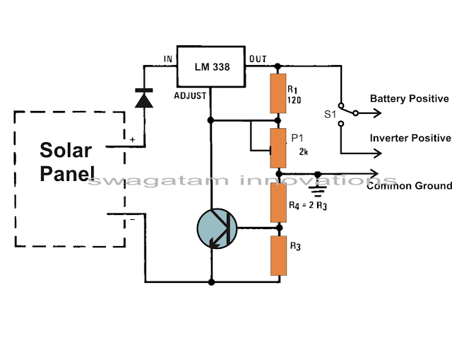
Referring to the figure we see a circuit design that utilizes very ordinary components and yet fulfills the needs just as required by our specs.
A single IC LM 338 becomes the heart of the entire configuration and becomes responsibly for implementing the desired voltage regulations single handedly.
The shown solar panel regulator, charger circuit is framed as per the standard mode of the IC 338 configuration.
The input is given to the shown input points of the IC and the output for the battery received at the output of the IC. The pot or the preset is used to accurately set the voltage level that may be considered as the safe value for the battery.
The circuit also offers a current control feature, which makes sure that the battery always receives a fixed predetermined charging current rate and is never over driven.
The module can be wired as directed in the diagram. The relevant positions indicated can be simply wired even by a layman. Rest of the function is taken care of by the regulator circuit.
The switch S1 should be toggled to inverter mode once the battery gets fully charged (as indicated over the meter).
The charging current may be selected by appropriately selecting the value of the resistors R3. It can be done by solving the formula:
0.6/R3 = 1/10 battery AH
The preset VR1 is adjusted for getting the required charging voltage from the regulator.