Showing posts with label voltage. Show all posts
Showing posts with label voltage. Show all posts
Monday, December 23, 2013
Build a Remotely Adjustable Solid State High voltage Supply Circuit Diagram
How to build a remotely adjustable solid state high-voltage supply Circuit Diagram. The output voltage changes approximately linearly up to 20 KV as the input voltage is varied from 0 to 5 V. The oscillator is tuned by a 5-0 potentiometer to peak the output voltage at the frequency of maximum transformer response between 45 and 55 kHz.
The feedback voltage is applied through a 100-KO resistor, an op amp, and a comparator to a high-voltage amplifier. A diode and varistors on the primary side of the transformer protect the output transistor. The transformer is a flyback-type used in color-television sets. A feedback loop balances between the high-voltage output and the low-voltage input.
Remotely Adjustable Solid State High-voltage Supply Circuit Diagram

Remotely Adjustable Solid State High-voltage Supply Circuit Diagram

Saturday, December 21, 2013
Battery Powered High voltage Generator Circuit Diagram
This is the battery powered high-voltage generator circuit diagram. Output voltage great enough to jump a l-inch gap can be obtained from a 12-V power source. A 555 timer IC is connected as an stable multi vibrator that produces a narrow negative pulse at pin 3. The pulse turns Ql on for the duration of the time period. The collector of Ql is direct-coupled to tbe base of tbe power transistor Q2, turning it on during the same time period.
The emitter of Q2 is direct -coupled through current limiting resistor R5 to the base of the power transistor. Q3 switches on, producing a minimum resistance between the collector and emitter. The high-current pulse going through tbe primary of high-voltage transformer Tl generates a very high pulse voltage at its secondary output terminal (labeled X). The pulse frequency is determined by tbe values of Rl, R2, and C2. The values given in the parts list were chosen to give the best possible performance when an auto-ignition coil is used for Tl.
Battery Powered High-voltage Generator Circuit Diagram

Thursday, September 26, 2013
Discrete Voltage Regulator
The title of this article naturally raises the question of why we think that the generous selection of fully integrated voltage regulators needs to be extended with a version constructed using discrete components. In other words, what does this circuit offer that the well-known ‘three-leggers’ don’t have? To start with, we can point out that this circuit is refreshingly simple for a discrete version. Three semiconductors, three resistors, a capacitor and a diode are all it needs. Of course, that’s still more components than an integrated regulator, so what exactly are the advantages of this circuit?
 They are to be found in three areas: voltage range, bandwidth and current rating. The last of these is the primary strength of this circuit, since the maximum current depends only on the specifications of the output transistor. With the BD680, as used here, a current of 4 A can be delivered at a collect-emitter voltage of 10 V with adequate cooling (Rth = 3.12 K/W). The peak current is even 6 A. Try matching that with an integrated voltage regulator! The maximum input voltage is 30 V with the illustrated version of the circuit (UDSmax of T1), but this can easily be increased by using special high-voltage transistors.
 The same applies to the bandwidth, which can be extended as desired, without any modifications to the circuit, by using high-speed transistors. Generally speaking, wide bandwidth is also not one of the strong points of integrated voltage regulators. As noted, the circuit is basically very simple. A zener diode (D1) fed with a constant current of around 1mA by a JFET current source (T1) provides the reference potential. C1 is connected in parallel with D1 to provide well-behaved startup behaviour (soft start). This capacitor also provides additional buffering and decouples noise and other disturbances. The startup time is around three seconds.
The only additional item that is needed for the voltage regulator is an output buffer for the reference potential. This takes the form of a sort of super-Darlington using T2 and T3. This works very well, but has the disadvantage that the output voltage is a bit lower (one diode drop) than the Zener voltage. P1 can be added to correct this, but this does reduce the regulation of the circuit. If the voltage difference is not important, it is thus better to replace P1 with a wire jumper. The main specifications of the voltage regulator are listed in Table 1.
Continue Reading[...]
 They are to be found in three areas: voltage range, bandwidth and current rating. The last of these is the primary strength of this circuit, since the maximum current depends only on the specifications of the output transistor. With the BD680, as used here, a current of 4 A can be delivered at a collect-emitter voltage of 10 V with adequate cooling (Rth = 3.12 K/W). The peak current is even 6 A. Try matching that with an integrated voltage regulator! The maximum input voltage is 30 V with the illustrated version of the circuit (UDSmax of T1), but this can easily be increased by using special high-voltage transistors.
 The same applies to the bandwidth, which can be extended as desired, without any modifications to the circuit, by using high-speed transistors. Generally speaking, wide bandwidth is also not one of the strong points of integrated voltage regulators. As noted, the circuit is basically very simple. A zener diode (D1) fed with a constant current of around 1mA by a JFET current source (T1) provides the reference potential. C1 is connected in parallel with D1 to provide well-behaved startup behaviour (soft start). This capacitor also provides additional buffering and decouples noise and other disturbances. The startup time is around three seconds.
The only additional item that is needed for the voltage regulator is an output buffer for the reference potential. This takes the form of a sort of super-Darlington using T2 and T3. This works very well, but has the disadvantage that the output voltage is a bit lower (one diode drop) than the Zener voltage. P1 can be added to correct this, but this does reduce the regulation of the circuit. If the voltage difference is not important, it is thus better to replace P1 with a wire jumper. The main specifications of the voltage regulator are listed in Table 1.
Wednesday, May 29, 2013
Voltage Booster Circuit Diagrams

This is voltage booster circuit diagram.you can get 24V from 12V DC.Q1 and Q2 are D1616.If you are unable to find D1616 You can use 2N 3055,C2236,SL 100.
Note
# For high current (around 5A) games use 2N 3055 transistor or more powerful Darlington pairs for Q1 and Q2.
Friday, May 17, 2013
MSK5012 Adjustable Voltage Regulator 10A

MSK5012 is a awful reliable adjustable voltage regulator.Whose achievement can be programmed application two resistors. The regulator has a actual low dropout voltage(0.45v @10A )due to the acceptance of MOSFT with actual low Rds (ON) as the centralized alternation canyon element.The MS5012 has a top akin of accurateness and ripple bounce is about 45dB. It is accessible in a 5 pin Sip amalgamation that is electrically abandoned from the centralized circuitry. This accord us the abandon to fit the IC anon to the calefaction bore and this array of absolute heatsinking improves the thermal dissipation.
The achievement voltage of this circuit is adjustable from 1.3v to 36v DC.Resistors R1 and R2 are acclimated for programming the achievement voltage. For all applications, amount of R2 is anchored to 10K. The accord amid R1,R2 and achievement voltage Vout is according to the blueprint R1=R2(Vout/1.235)-1. C1 is a clarify capacitor which is aswell a allotment of the aboideau drive circuit of the centralized alternation canyon MOSFET. About three times the ascribe voltage will arise beyond this capacitor and so the its voltage appraisement have to be called accordingly.C2 is the ascribe clarify capacitor while C3 is the achievement clarify capacitor.
Thursday, April 11, 2013
Dual Voltage Power Supply 12 Volt
This is the straightforward circuit diagram of Dual Voltage\r\n Power Supply. It is used for Misc… software. This circuit is known as \r\nregulated energy provide. For this reason the principle portion of this \r\ncircuit is Regulator IC. It also needs few parts to constructed. The regulator 7812 is the certain voltage regulator and 7912 is the bad voltage regulator.

It regulates voltage from 24Volt to 12 Volt (DC). The transformer\r\n enter is 110Volt to 220Volt (AC) and the output need to be between 12Volt \r\nto 24Volt (AC) and present need to be 500mA. In this circuit some \r\ncapacitors are used as a filter for disposing of repole.
Wednesday, April 10, 2013
Transistor Basic Voltage Regulator Circuit
 The transistors series voltage regulator circuit is shown in the picture. And, the picture (a) is equivalent circuit. The VT1 is adjustment transistor which is used to adjust the output voltage. The VT1 and load RL are in series. So this circuit is called the series voltage regulator circuit. Because the adjustment tube is using the transistors, the transistor series voltage regulator circuit could work under a big working current which could overcome the weakness that the zener diode regulator circuits output current is limited by the zener diode limiting current. The picture (b) is the practical series voltage regulator circuit. The picture (c) is its diagram circuit.
Sunday, April 7, 2013
Simple Source Voltage Protector

Protection of electronic devices with a DC voltage source of voltage source obligatory reversal, especially protection of the source voltage is reversed. The definition of "Protectors Voltage Sources" in this article are the source voltage surge protector circuit which serves to protect the device from the reversal of the voltage source to the appliance electronics.
Source voltage surge protector will expressed in this article are general, so that later in their applications to stay adjusted value of the component with the voltage source needs an electronic appliance. Let us start reviewing Protectors Voltage Source by simple and modest.
 |
| Source voltage protection with 1 diode |
Diodes are used as a protector of the source voltage installation tebaliknya voltage source is installed in series with the input line voltage source electronics devices. Installation of surge protector diode as a voltage source is on the positive line voltage source input device. The function is to drain diode current (voltage source) in one direction only, so that in the event of an upside-down voltage source. then the voltage source is not in the channel (in blocks) to the device. The value of the diode is tailored to the needs of the source voltage of the device itself.
 |
| Source voltage protection with dioda bridge |
Protectors voltage source with a diode bridge in principle the same as the surge protector with a voltage source diode 1 pc. The difference is the source voltage surge protector is not blocking the source voltage, but the source voltage surge protector is to reverse the flow of the source voltage of one polarity in the case of voltage source. From the picture above to explain the purpose of reversing the voltage source in question, namely when given a source voltage through a voltage surge protector is the source of positive polarity (+) will be directly in the stream leading to the positive input line of tools and the source of negative voltage (-) will be directed to the negative voltage source input line tool.
Low Power Voltage Doubler Circuit Diagram
All
miniature electronic devices operate off batteries. Some of them need
higher than the standard battery voltages to operate efficiently. If
the battery of that specific voltage is unavailable, we are forced to
connect additional cells in series to step up the DC voltage. Thus, the
true meaning of miniaturisation is lost. A simple way to overcome this
problem is to employ a voltage doubler, if the device under
consideration can operate at a small current.
Here we present a
low-power voltage doubler circuit that can be readily used with devices
that demand higher voltage than that of a standard battery but low
operating current to work with. The circuit is quite simple as it uses
only a few components. Yet, the output efficiency is 75 to 85 percent
along its operating voltage range. The available battery voltage is
almost doubled at the output of the circuit.
Here IC1 is wired as
an astable multivibrator to generate rectangular pulses at around 10
kHz. This frequency and duty cycle of the pulses can be varied using
preset VR1. The pulses are applied to switching transistors T1 and T2
for driving the output section, which is configured as a
voltage-doubling circuit. The doubled voltage is available across
capacitor C5. During each cycle of the pulse occurance, the high level
drives T1 into its saturation, keeping transistor T2 cut off.
Circuit diagram:

So
transistor T1 charges capacitor C4 via the path formed by diodes D2
and D1 to a voltage level slightly lesser than the supply. But during
the low period of the pulse, transistor T1 is cut off while transistor
T2 is driven into saturation. Now, transistor T2 raises the charge on
the negative pole of capacitor C4 by another step equal to the supply
voltage. Therefore an equal amount of charging is built up on capacitor
C5 via diode D3.
This doubling action increases the total
voltage across capacitor C5 to almost double the input voltage. If the
output of the pulse generator is maintained with a high enough
amplitude and frequency, the output voltage and current remain constant
and cater to the needs of the load. Even with the half-wave function,
this circuit is almost free of ripple voltage. If the connected load
doesn’t require a high current, the efficiency can be expected in the
upper 90 percentranges.
Since the input voltage is doubled, the
current drain from the input power supply is also doubled at the input
but halved at the output. One point of caution is that if the
multivibrator’s frequency is fairly high, the output may suffer with the
interference imposed over the DC voltage. In this case, the frequency
must be set favorably by trials and actual load connection procedure.
This tiny circuit can be assembled on the general-purpose PCB. If all of
the components are surface-mount type, the whole module can be
genuinely miniaturized.
EFY Lab note.
During testing with input of 8V and 1.25mA load current the output voltage was found to be around 13V.
Source: EFY Mag
miniature electronic devices operate off batteries. Some of them need
higher than the standard battery voltages to operate efficiently. If
the battery of that specific voltage is unavailable, we are forced to
connect additional cells in series to step up the DC voltage. Thus, the
true meaning of miniaturisation is lost. A simple way to overcome this
problem is to employ a voltage doubler, if the device under
consideration can operate at a small current.
Here we present a
low-power voltage doubler circuit that can be readily used with devices
that demand higher voltage than that of a standard battery but low
operating current to work with. The circuit is quite simple as it uses
only a few components. Yet, the output efficiency is 75 to 85 percent
along its operating voltage range. The available battery voltage is
almost doubled at the output of the circuit.
Here IC1 is wired as
an astable multivibrator to generate rectangular pulses at around 10
kHz. This frequency and duty cycle of the pulses can be varied using
preset VR1. The pulses are applied to switching transistors T1 and T2
for driving the output section, which is configured as a
voltage-doubling circuit. The doubled voltage is available across
capacitor C5. During each cycle of the pulse occurance, the high level
drives T1 into its saturation, keeping transistor T2 cut off.
Circuit diagram:

Low-Power Voltage Doubler Circuit Diagram
So
transistor T1 charges capacitor C4 via the path formed by diodes D2
and D1 to a voltage level slightly lesser than the supply. But during
the low period of the pulse, transistor T1 is cut off while transistor
T2 is driven into saturation. Now, transistor T2 raises the charge on
the negative pole of capacitor C4 by another step equal to the supply
voltage. Therefore an equal amount of charging is built up on capacitor
C5 via diode D3.
This doubling action increases the total
voltage across capacitor C5 to almost double the input voltage. If the
output of the pulse generator is maintained with a high enough
amplitude and frequency, the output voltage and current remain constant
and cater to the needs of the load. Even with the half-wave function,
this circuit is almost free of ripple voltage. If the connected load
doesn’t require a high current, the efficiency can be expected in the
upper 90 percentranges.
Since the input voltage is doubled, the
current drain from the input power supply is also doubled at the input
but halved at the output. One point of caution is that if the
multivibrator’s frequency is fairly high, the output may suffer with the
interference imposed over the DC voltage. In this case, the frequency
must be set favorably by trials and actual load connection procedure.
This tiny circuit can be assembled on the general-purpose PCB. If all of
the components are surface-mount type, the whole module can be
genuinely miniaturized.
EFY Lab note.
During testing with input of 8V and 1.25mA load current the output voltage was found to be around 13V.
Source: EFY Mag
Saturday, April 6, 2013
7812 voltage stabilizer
 To obtain a pure DC voltage, then we must consider the regulation voltages and currents that we change from AC to DC current. For that we need some settings that can support our own making and its components were easy to get in the electronics market.
This is series Power Supply that can be used on trafo 5 Ampere up to 10 Amperes.

If you want to use a larger transformer than 5 Amperes transistor 2N3055 is suggested that the double for the exit of the collector current is larger and in accordance with the current out of the transformer. How pemasanganya enough in the series on all sides of the pin.
Friday, April 5, 2013
How to Build a Solar Panel Voltage Regulator Charger Circuit Charger Circuit at Home
How to Build a Solar Panel Voltage Regulator, Charger Circuit, Charger Circuit at Home
We all know pretty well about solar panels and their functions. The basic functions of these amazing devices is to convert solar energy or sun light into electricity.
Basically a solar panel is made up discrete sections of individual photo voltaic cells. Each of these cells are able to generate a tiny magnitude of electrical power, normally around 1.5 to 3 volts.
Many of these cells over the panel are wired in series so that the total effective voltage generated by the entire unit mounts up to an usable 12 volts or 24 volts outputs.
The current generated by the unit is directly proportional to the level of the sun light incident over the surface of the panel.
The power generated from a solar panel is normally used for charging a lead acid battery. The lead acid battery when fully charged is used with an inverter for acquiring the required AC mains voltage for powering the house electrical.
Ideally the sun rays should be incident over the surface of the panel for it to function optimally. However since the sun is never still, the panel needs to track or follow the suns path constantly so that it generates electricity at an efficient rate.
If you are interested to build an automatic dual tracker solar panel system you may refer one of my earlier articles. Without a solar tracker, the solar panel will be able to do the conversions only at around 30 % efficiency.
Coming back to our actual discussions about solar panels, this device may be considered the heart of the system as far converting solar energy into electricity is concerned, however the electricity generated requires a lot of dimensioning to be done before it can be used effectively in the preceding grid tie system.
The voltage acquired from a solar panel is never stable and varies drastically according to the position of the sun and intensity of the sun rays and of course on the degree of incidence over the solar panel.
This voltage if fed to the battery for charging can cause harm and unnecessary heating of the battery and the associated electronics; therefore can be dangerous to the whole system.
In order to regulate the voltage from the solar panel normally a voltage regulator circuit is used in between the solar panel output and the battery input. This circuit makes sure that the voltage from the solar panel never exceeds the safe value required by the battery for charging.
Normally to get optimum results from the solar panel, the minimum voltage output from the panel should be higher than the required battery charging voltage, meaning even during adverse conditions when the sun rays are not sharp or optimum, the solar panel still should be able to generate a voltage more than say 12 volts which may be the battery voltage under charge.
Solar Voltage regulators available in the market can be too costly and not so reliable; however making one such regulator at home using ordinary electronic components can be not only fun but also very economical.
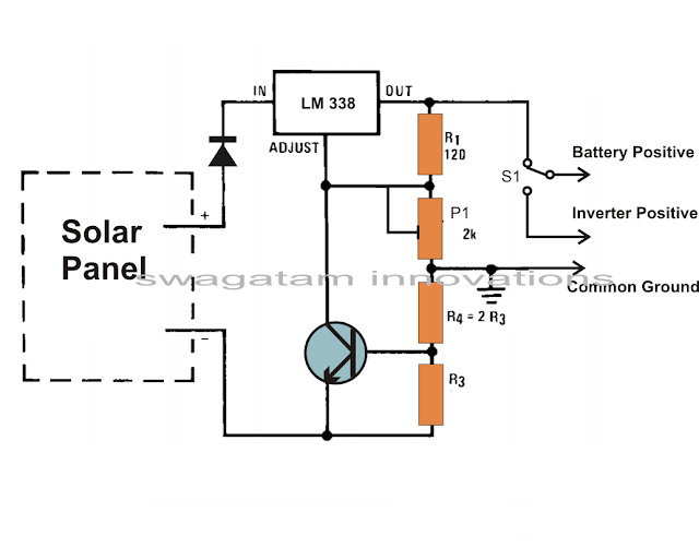
Referring to the figure we see a circuit design that utilizes very ordinary components and yet fulfills the needs just as required by our specs.
A single IC LM 338 becomes the heart of the entire configuration and becomes responsibly for implementing the desired voltage regulations single handedly.
The shown solar panel regulator, charger circuit is framed as per the standard mode of the IC 338 configuration.
The input is given to the shown input points of the IC and the output for the battery received at the output of the IC. The pot or the preset is used to accurately set the voltage level that may be considered as the safe value for the battery.
The circuit also offers a current control feature, which makes sure that the battery always receives a fixed predetermined charging current rate and is never over driven.
The module can be wired as directed in the diagram. The relevant positions indicated can be simply wired even by a layman. Rest of the function is taken care of by the regulator circuit.
The switch S1 should be toggled to inverter mode once the battery gets fully charged (as indicated over the meter).
The charging current may be selected by appropriately selecting the value of the resistors R3. It can be done by solving the formula:
0.6/R3 = 1/10 battery AH
The preset VR1 is adjusted for getting the required charging voltage from the regulator.
Subscribe to:
Posts (Atom)