Friday, April 12, 2013
Simple Transistor Tester

This non transistor tester circuit devices that isn’t accurate, but utility of this test device enough assisting in assaying of quality of transistor. This circuit can show promise about condition of a transistor is still in condition either or have been in condition of breakdown. Besides, earns also applied to test amplification of current from the transistor is categorizing transistor type A (amplifier of current 140 - 270), transistor type B (270 - 500), or transistor type C (amplification > 500).
For example earns we to take a n p-n transistor as transistor which will be tested. The transistor packed into socket appropriate TUT = Transistor Under Test) hereinafter switches S2 is attached according to at schematic. If LED D2 blazed, hence the transistor is type C, medium if LED didnt ON, switches S2 must be removed on course middle and if still had not blazed, removes switches to last position. If LED is ON at course last switches, means transistor is type A.
On the contrary, if LED remaining to extinguish though had been tested at all of position of switches, hence transistor had been in condition of breakdown or has amplification of current smaller than 140, so that for transistor having small signal basically cann’t be utilized. Bases current to transistor is being tested able to be broken by using switches using compress switches. If LED still in condition blazed, means happened links shortening between colector and emitor at the transistor.
This very simple circuit work principle. Transistor tested receives bases current around 10mA through R1. With assumption that transistor is still be good, the thing will yield strain at R2 until R4 and depend on position of switches S2, some of this voltage compared to to a reference voltage by utilizing IC 1. Mode of action from circuit which its inside is also approximately equal, only inside of circuit destined for PNP transistor. The supply of the voltage is required by this circuit only from battery.
Wednesday, April 10, 2013
Transistor Basic Voltage Regulator Circuit
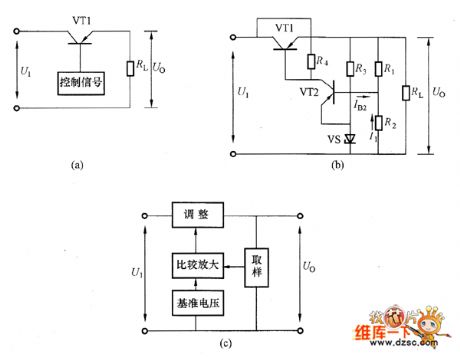 The transistors series voltage regulator circuit is shown in the picture. And, the picture (a) is equivalent circuit. The VT1 is adjustment transistor which is used to adjust the output voltage. The VT1 and load RL are in series. So this circuit is called the series voltage regulator circuit. Because the adjustment tube is using the transistors, the transistor series voltage regulator circuit could work under a big working current which could overcome the weakness that the zener diode regulator circuits output current is limited by the zener diode limiting current. The picture (b) is the practical series voltage regulator circuit. The picture (c) is its diagram circuit.
 Sunday, April 7, 2013
Two transistor tone controller

The operation of the circuit is the transistor Q1 is wired an emitter follower to provide sufficient current gain and input impedance. The second transistor is used to voltage amplify the signal in. The network of resistance and capacitors connected between emitter of Q1 and base of Q2 is used to control the tone. Variation in the value of these components varies the audio response of the system. This circuit can provide a maximum attenuation and boost of 10decibel on 10 KHz and 60 Hz frequency ranges. The input and output must be connected with respect the ground. POT R5 can be used to control bass. POT R8 can be used to control treble.