Monday, September 2, 2013
2 Cell Lithium Ion Charger
When the battery is low, the current pulses are spaced close together so that a somewhat constant current is present. As the batteries reach full charge, the pulses are spaced farther apart and the full charge condition is indicated by the LED blinking at a slower rate. A TL431, band gap voltage reference (2.5 volts) is used on pin 6 of the comparator so the comparator output will switch low, triggering the 555 timer when the voltage at pin 7 is less than 2.5 volts.
The 555 output turns on the 2 transistors and the batteries charge for about 30 milliseconds. When the charge pulse ends, the battery voltage is measured and divided down by the combination 20K, 8.2K and 620 ohm resistors so when the battery voltage reaches 8.2 volts, the input at pin 7 of the comparator will rise slightly above 2.5 volts and the circuit will stop charging.
2 Cell Lithium Ion Charger Circuit diagram

The circuit could be used to charge other types of batteries such as Ni-Cad, NiMh or lead acid, but the shut-off voltage will need to be adjusted by changing the 8.2K and 620 ohm resistors so that the input to the comparator remains at 2.5 volts when the terminal battery voltage is reached. For example, to charge a 6 volt lead acid battery to a limit of 7 volts, the current through the 20K resistor will be (7-2.5)/ 20K = 225 microamps. This means the combination of the other 2 resistors (8.2K and 620) must be R=E/I = 2.5/ 225 uA = 11,111 ohms. But this is not a standard value, so you could use a 10K in series with a 1.1K, or some other values that total 11.11K
Be careful not to overcharge the batteries. I would recommend using a large capacitor in place of the battery to test the circuit and verify it shuts off at the correct voltage.
Friday, August 9, 2013
Mobile Phone and iPod Battery Charger
Charge your iPod without connecting it to a computer!
Using the USB port on your computer to charge your player’s batteries is not always practical. What if you do not have a computer available at the time or if you do not want to power up a computer just for charging? Or what if you are traveling? Chargers for Mobile Phones iPods and MP3 players are available but they are expensive and you need separate models for charging at home and in the car.
This charger can be used virtually anywhere. While we call the unit a charger, it really is nothing more than a 5V supply that has a USB outlet. The actual charging circuit is incorporated within the iPOD or MP3 player itself, which only requires a 5V supply. As well as charging, this supply can run USB-powered accessories such as reading lights, fans and chargers, particularly for mobile phones.
The supply is housed in a small plastic case with a DC input socket at one end and a USB type "A" outlet at the other end, for connecting to Mobile Phone, an iPod or MP3 player when charging. A LED shows when power is available at the USB socket. Maximum current output is 660mA, more than adequate to run any USB-powered accessory.
Pictures, PCB and Circuit Diagram:
 Front View Of Mobile Phone and iPod Battery Charger Circuit
 Bottom View Of Mobile Phone and iPod Battery Charger Circuit
 PCB Layout Of Mobile Phone and iPod Battery Charger Circuit
 Mobile Phone and iPod Battery Charger Circuit Diagram
| Parts | Description |
| P1 | 1K |
| R1 | 1R-0.5W |
| R2 | 1R-0.5W |
| R3 | 1R-0.5W |
| R4 | 1K |
| R5 | 560R |
| R6 | 10R-0.5W |
| R7 | 470R |
| C1 | 470uF-25V |
| C2 | 100nF-63V |
| C3 | 470pF |
| C4 | 100uF-25V |
| D1 | 1N5404 |
| D2 | 1N4001 |
| D3 | 1N5819 |
| D4 | 5.1V-1W Zener Diode |
| D5 | 5mm. Red LED |
| L1 | 220uH |
| S1 | USB A Type Socket |
| SW1 | On/Off Switch |
| IC1 | MC34063A |
Specifications:
Output voltage ----------------------5V
Output current ---------------------660mA maximum for 5V out
Input voltage range ------------------9.5V to 15V DC
Input current requirement ----------500mA for 9V in, 350mA for >12V input
Input current with output shorted--- 120mA at 9V in, 80mA at 15V in
Output ripple ------------------------14mV (from no load to 660mA)
Load regulation ----------------------25mV (from no load to 660mA)
Line regulation ----------------------20mV change at full load from 9 to 18V input
No load input current ----------------20mA
(The specification for the computer USB 2.0 port requires the USB port to deliver up to 500mA at an output voltage between 5.25V and 4.375V).
The circuit is based around an MC34063 switch mode regulator. This has high efficiency so that there is very little heat produced inside the box, even when delivering its maximum output current. The circuit is more complicated than if we used a 7805 3-terminal regulator but since the input voltage could be 15V DC or more, the voltage dissipation in such a regulator could be 5W or more at 500mA. and 5W is far too much for a 7805, even with quite a large heatsink. Credit for this circuit goes to SiliconChip, A wonderful electronics magazine.
Source :www.extremecircuits.net
Monday, April 8, 2013
12 Volt Charger Circuit with LM350

Friday, April 5, 2013
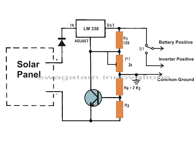
How to Build a Solar Panel Voltage Regulator Charger Circuit Charger Circuit at Home
How to Build a Solar Panel Voltage Regulator, Charger Circuit, Charger Circuit at Home
Many of these cells over the panel are wired in series so that the total effective voltage generated by the entire unit mounts up to an usable 12 volts or 24 volts outputs.
Thursday, April 4, 2013
Broken Charger Connection Alarm
 Broken Charger Connection Alarm Circuit Diagram
| Parts | Description |
| R1 | 10K |
| R2 | 1K |
| R3 | 1K |
| Q1 | BC557 |
| Q2 | BC557 |
| D1 | 1N4007 |
| D2 | 1N4007 |
| D3 | Red LED |
| BZ1 | Piezo Sounder |
- An optional LED and its series limiting resistor can be wired in parallel to BZ1, as shown in dotted lines in the circuit diagram.
- In this case you may omit the Piezo-sounder in order to obtain a visual alert only.
Tuesday, April 2, 2013
Automobile Head Light Dipper with Cell Phone Charger Circuit
The following brief explanation was provided by Miss Surya for getting a better view of the proposed circuit design of an automobile automatic dimmer cum dipper head light switch circuit with an optional cell phone charger circuit for facilitating the charging of a cell phone also on board.
Circuit Description
Here the IC 555 has been used not as a charging indicator rather as a comparator for controlling the dipping action of the head lamps.
The use if IC 555 as a charging indicator would have made the circuit unnecessarily complicated, therefore a novel and simpler way is selected for the charging ON indication.
The LED connected across the 5 Ohm watt current limiting resistor effectively indicates the charging status of the cell phone and switches OFF the moment the charging process stops.
The IC 555 works like a comprartor here, when light falls on the LDR, voltage at PIN#2 rises above the set internal threshold which prompts the IC to change its output PIN#3 voltage from 0 to 12, triggering the connected relay.
The relay contacts immediately transfer the positive supply from the "high" filament to the "low" filament of the head lamps, resulting in an instant dipping of the lamp intensity.
The LDR must be positioned in such a way that it only receives light rays coming from front of the vehicle, which will be mostly the lights from another vehicles head lamps.

Sunday, March 31, 2013
Electric Window Fence Charger
Here is the circuit of a simple electric window charger. With a couple of minor circuit variations, it can be used as an electric fence charger too. A standard 12V, 7Ah sealed maintenance-free (SMF) UPS battery is required for powering the entire unit. Any component layout and mounting plan can be used. However, try to keep the output terminals of transformer X1 away from the circuit board. Timer NE555 (IC1) is wired as a free-running oscillator with narrow negative pulse at the output pin 3. The pulse frequency is determined by resistors R2 and R3, preset VR1 and capacitor C3. The amplitude of the output pulse can be varied to some extent by adjusting variable resistor VR1. You can vary the frequency from 100 Hz to 150 Hz. X1 is a small, iron-core, step-down transformer (230V AC primary to 12V, 1A secondary) that must be reverse connected, i.e., the secondary winding terminals of the transformer should be connected between the emitter and ground and the output taken across the primary winding.
Circuit diagram:
 Electric Window/Fence Charger Circuit diagram
Switch S1 is used for power ‘on’/‘off’ and LED1 works as a power-‘on’ indicator. LED2 is used to indicate the pulse activity. The output pulse from pin 3 of IC1 drives pnp transistor T1 into conduction for the duration of the time period. The collector of T1 is connected to the base of driver transistor T2 through resistor R5. When transistor T1 conducts, T2 also conducts. When T2 conducts, a high-current pulse flows through the secondary winding of transformer X1 to generate a very high-voltage pulse at the primary winding. This dangerously high voltage can be used to charge the window rails/fences. Ordinary silicon diode D1 (1N4001) protects T2 against high-voltage peaks generated by X1 inductance during the switching time. You can replace X1 with another transformer rating, and, if necessary, replace T2 with another higher-capacity transistor. The circuit can be used to charge a 1km fence with some minor modifications in the output section.
Caution:Take all the relevant electrical safety precautions when assembling, testing and using this high-voltage generator.
Author: T.K. Hareendran Source :e f y m a g